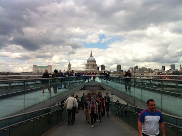
Long axis of the Millennium Bridge by Oliver Broadbent is licensed under CC BY-NC-SA 4.0
One of the groups of students that Ben Godber and I teach at the University of Southampton is designing a stressed ribbon footbridge as their entry for a design competition we’ve set them. A stressed ribbon is bridge is like a very shallow suspension bridge, the difference is that once the deck units are attached, the tension in the cables is ratcheted up, squashing the deck units together. The benefit of this post-tensioning is that it can greatly reduce the sag in the bridge, creating a much flatter bridge.
The students’ proposal is an elegant response to the site, but they have come up against the problem that they don’t know how to calculate the forces in the cables and so they can’t design the bridge. I was talking to my colleague Chris Wise about this problem of students not being able to design what they draw (a common student response apparently is that because they have seen a similar design online, they know it can be done: job done). But what Chris tells me he tells his students is that they should be able to justify every line that they draw. To help them, he provides students with an engineer’s toolbox, a handout full of rules of thumb that allow student engineers to draw engineering structures in roughly the right dimensions the first time around.
Returning to the case of our student’s stressed ribbon bridge, the bit of mechanics they need to understand is the equation that links the sag in a catenary cable with the horizontal force at the supports. For a static load on a single span bridge, this is easy to calculate, and is given by the equation Fh = wL^2/8s (where ‘w’ is the line load; ‘L’ is the length of the span; and ’s’ is the sag in the cable). Plugging the numbers into this equation gives what the horizontal pull of the cables at either end. The picture is however complicated when there are there are three unequal spans with the cables running continuously over the two supports in the river. If the cable is continuous, the tension in the cable must be equal either side of the support. If that is the case, then for a fixed load on the bridge, the sag in the spans needs to be adjusted to ensure the horizontal forces in the cables at the point where they go over the supports is equal on either side.
Were you to create a physical model of this scenario in which two people hold a chain that is draped across a pair of stools, the chain would adjust it’s own position until it finds its own equilibrium. To find this equilibrium in the design process, engineers do what’s called form-finding, an iterative process in which the parameters of the design are adjusted until all the forces are in equilibrium. For the purposes of a student project, a good-enough result can be obtained by setting up a spreadsheet to do the horizontal force calculations, and to iteratively adjust the sag in the cables until the forces balance.
There’s one final catch though. The process I’ve just described assumes the load on the bridge is constant; however, loads on a bridge change according to how people are using it. Engineers look for worse-case scenarios: the pattern of loading that would create the most difficult load for the bridge to carry. For instance, one worse-case scenario for a footbridge might be all the users standing against one edge watching a boat race, and then all at once, running to the other edge as the boats pass underneath. In the students’ scenario, the students need to think about how they will accommodate any difference in loading between the spans. If they were to leave the cables to free slide back and forth over the central supports, then as the loading changes the sags in the bridge spans would increase or decrease, which would be quite uncomfortable for the user! The alternative is to clamp the cables down on the tops of the supports. Any difference in the tension between the two spans due to unequal loading will then cause the column to be pulled sideways one way or another. The columns can be designed to resist these overturning forces. The challenge for the students is to work out what worse-case scenarios would exist to cause this unbalance in the cable forces.
Of course, everything above is greatly simplified. I don’t pretend to know the details of how to design a stressed ribbon bridge and I am grateful to my colleague Andrew Weir who helped me understand the mechanics of the problem in such a way that I can easily explain it to my students. The point is to illustrate what I think is one of the most important things that students can learn from design projects at university, and that is the ability to use their knowledge of mechanics and their experience of the world to develop a plausible response to a project. It is also one the areas of teaching that I enjoy the most because it best illustrates what an engineer can do: combining their own experience with an understanding of how things work to shape the world around them.


Leave a Reply