Category: Engineering (old category)

  • Sorting out your lego – the Eiffelover guide

    Sorting out your lego – the Eiffelover guide

    image

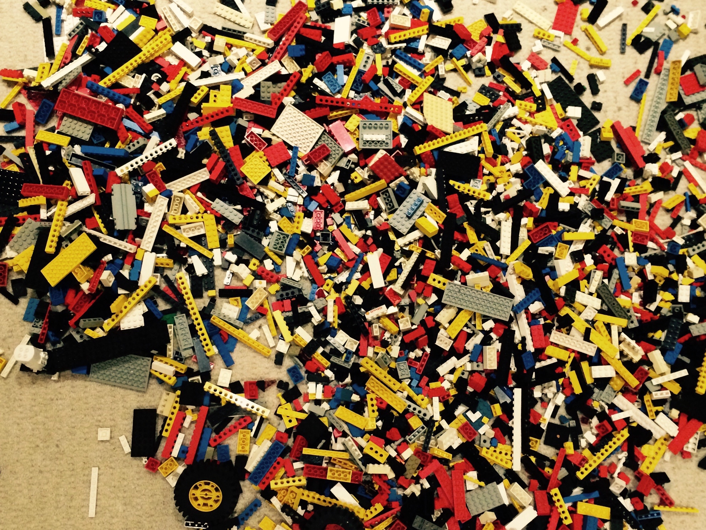
    If you own a big pile of Lego, then sorting it into separate boxes for different sorts of parts makes it much quicker for you to build anything you want to. I have found that the creative potential my haul of lego is multiplied manyfold by the simple act of separating it out. All of a sudden, when I can see what types of pieces I have, the ideas flow much more quickly, and the time lag between having the idea, and it manifesting itself in physical form is much reduced.

    The question is knowing where to start. There are so many types of pieces, it doesn’t work to have a pot for every single type. I’ve probably completely sorted my Lego three times in my life (so far), and I think the categories that I have now are pretty effective. So to save you thre trouble, here they are.

    Helpfully, since the first time I sorted  my Lego, the Internet has been invented, and so it is now much easier to find commonly agreed names for pieces. In the lists below I’ve included some links to to photos of the pieces that I am talking about. I’ve organised the following list according to the size of tub I needed for each part. It’s the relative size that’s important here.

    8L tubs

    Base plates

    • Lunar landscapes
    • Road pieces
    Miscellaneous
    • Train buffers
    • Rigging
    • Pirate ship hull
    • Pirate ship sails
    • Pirate ship masts
    • Monorail track and pylons
    • Train track

    4L tubs

    Bricks
    These are your standard building bricks. You would think that the protypical lego brick would be the most common, but compared to other bits I have relatively few of these. 2 by X bricks (X>1)
    Wheels and tyres
    This is for wheels of all shapes and sizes, their tyres and the plates with axle stubs attached onto which little wheels and wagon wheels can be fixed. This is the biggest tub of all.
    Large plates
    For those large base plates that are at least 4×4
    Narrow long bricks
    These are like beams. These are 1 bx X bricks where X>3, but with no side holes
    Narrow long bricks with holes
    As above but with holes in so you can push through axles.
    Small bricks
    This is probably the modal category of my lego bricks. You are much more likely to find one of these than a standard 2×2 brick. Includes:
    Wide plates
    I think of these as planks 2 x X where X>1
    Narrow plates
    These are thin plates – 1x X where  X>3

    2L tubs

    Automotive paraphernalia
    Space paraphernalia
    Pieces for making space rockets and space stations, such as

    1L tubs

    Little plates
    These are among the smallest pieces
    Slopes and arches
    There are lots of variations of arches and slops, and the nomenclature can become a bit confusing.
    Round bits
    There is some ambiguity as to whether some of these pieces should really go under space paraphernalia.
    • 1×1 cones
    • 1×1 round brick
    • 2×2 cone
    • 1×1 round plates
    • 2×2 round plates
    • 2×2 round brick
    • antenna
    • 2×2 curved brick
    • 4x4x2 cone
    Hinges
    When I was a kid, hinges were my favourite part. Now I have a whole box full of them. They include:
    People and their accessories
    A box full of Lego people is always fun just to play with on its own. I throw in all the accessories too such as:
    • Shield
    • Spear
    • Sword
    • Cutlas
    • Lance
    • Torch
    • Knight’s helmet flame
    • Musket
    • Pistol
    • Oar
    • Spanner
    • Hammer
    • Broom brush
    Pirate/medieval 
    • Horse harness
    • Flag with 2 clips
    • Streamer (type of flag)
    • Barrels
    • Treasure chest
    • Treasure
    • Canon
    • Castle panel sides
    • 3×3 angled corner brick
    Windows and doors
    • Includes hinges for windows and shutters too.
    Town
    Parts for building suburbia
    • Mailbox with door
    • 2×4 winch
    • Street furniture
    • Car wash pieces
    • Long fencing
    • Petrol station parts
    • Emergency services parts
    • Roadworks parts
    Flora and forna
    • Small tree
    • Conifer
    • Flowers and stem
    • Palm tree leaf
    • Sharks
    • Monkeys

    0.5L tubs

    Holders
    Pieces for clipping things too, like personal accessories
    • 2×3 curved plate with hole
    • 1×1 plates with vertical clip
    • 1×1 plate with horizontal clip
    • 1×2 plate with vertical bar
    • 1×2 tile with top bar
    • 1×2 plate with handled bar
    • 2×2 brick with ball joint
    Wall elements
    • These are the pieces that make up the walls of castles and the sides of vans and trucks
    Lattice fences
    • 1x4x1 lattice fence
    • 1x4x2 lattice fence
    Lights
    • Transluscent pieces usually used for making headlights and tail lights
    Light holders
    • 1×1 brick with 1 side stud
    • 1×1 plate with side ring
    Small tiles
    • 1×1 tiles
    • 1×2 tiles
    • 2×2 tiles
    Long tiles
    • 1xX tiles where X>2
    Angle plates
    • 1×2/1×4 Angle plate
    Turntables
    • 2×2 turntable
    • 4×4 turntable
    Axles
    • Cross Axles
    • Threaded cross axles
    Things that go on cross axles
    • Gears
    • Right angle axle connector
    • Collars
    Pins
    • Half pin
    • Grey pin
    • Black pin
  • HS2, Seneca and the art of persuasion

    HS2, Seneca and the art of persuasion


    Persuasion is an important skill for designers: to convince the audience of an idea is it to allow it take root and evolve. Unfortunately, I never have been convinced of my persuasive powers, which is why I am always on the look out for useful tools of persuasion. The following two approaches from very different sources caught my attention this week. Add them to your thinking toolkits if you think they are of use.

    The case High Speed 2 and the Overton Window

    I first read about the concept of the Overton Window in Owen Jones’s excellent book, ‘The Establishment’. The Overton Window is the range of ideas that the public will accept. This range is not necessarily fixed and can be stretched or shifted one way or the other. Jones argues that the UK ‘establishment’ has successfully shifted the Overton Window in the UK by supporting pressure groups that consistently present in the media opinions to the right of popular acceptability. Over time and exposure these once-extreme views become more acceptable, shifting the Overton Window to the right. In this article from the US National Review the author claims the Overton Window in the US is moving the other way, although I can’t say I agree.

    From an engineering design point of view, it is interesting to see how the high-speed rail Overton Window has shifted, as described by Simon Jenkins in his article ‘HS2: the zombie train that refuses to die’. When the first enthusiasts started proposing high-speed rail in the 80s, the railways were in decline – it was an extreme view. Then, little by little, things nudged the terms of the debate towards acceptability: the construction of the channel tunnel; the lack of high-speed line to the tunnel; the eventual opening of the first high-speed line to the tunnel; how high-speed rail could see off the need for a third runway at Heathrow. Eventually, the terms of the debate shifted from whether or not to have a high-speed line, to which route it would take.

    And so, there we have persuasive tool number one. It is possible to shift an audience to your way of thinking by consistently and repeatedly advocating ideas that are just beyond acceptability and looking for small wins that slowly shift the Overton Window in your favour. Think of it more as a stopping train than a high-speed approach.

    Seneca says don’t be scruffy

    My second persuasive tool is not so much a technique but a starting point and comes from Seneca’s ‘Letters from a Stoic’. In his fifth letter he advises his correspondent to

    “avoid shabby attire, long hair, an unkempt beard, an outspoken dislike of silverware, sleeping on the ground and all other misguided means to self-advertisement”

    The aim of his advice is to make his friend, a fellow philosopher, more acceptable in appearance to his audience so that he may may have more influence over them. He goes on,


    “Let our way of life be not diametrically opposed to, but better than that of the mob. Otherwise we shall repel and alienate the very people whose reform we desire”.

    And so there we have our second tool of persuasion: don’t be so extreme as to put people off. Be of them, be recognisable to them so that they might accept you.

    Acceptable unacceptability?

    I encountered these two approaches in the same week, and initially thought them opposed: one is to champion views from the extremes and draw people towards them; the other is to champion views from a position of acceptability. So which is better?

    Seneca anticipates and resolves this paradox for us by recommending that,

    “one’s life should be a compromise between the ideal and the popular morality. People should admire our way of life but they should at this time find it understandable.”

    So perhaps where these approaches meet, and where designers should aim for is acceptable unacceptability.

    Related posts

  • The view from More London

    The view from More London

    It’s a curious place, More London.


  • Stressed by stressed ribbons – teaching notes from Southampton

    Stressed by stressed ribbons – teaching notes from Southampton

    St Paul's in the distance viewed via the long axis of the Millennium Bridge
    Long axis of the Millennium Bridge by Oliver Broadbent is licensed under CC BY-NC-SA 4.0

    One of the groups of students that Ben Godber and I teach at the University of Southampton is designing a stressed ribbon footbridge as their entry for a design competition we’ve set them. A stressed ribbon is bridge is like a very shallow suspension bridge, the difference is that once the deck units are attached, the tension in the cables is ratcheted up, squashing the deck units together. The benefit of this post-tensioning is that it can greatly reduce the sag in the bridge, creating a much flatter bridge.

    The students’ proposal is an elegant response to the site, but they have come up against the problem that they don’t know how to calculate the forces in the cables and so they can’t design the bridge. I was talking to my colleague Chris Wise about this problem of students not being able to design what they draw (a common student response apparently is that because they have seen a similar design online, they know it can be done: job done). But what Chris tells me he tells his students is that they should be able to justify every line that they draw. To help them, he provides students with an engineer’s toolbox, a handout full of rules of thumb that allow student engineers to draw engineering structures in roughly the right dimensions the first time around.

    Returning to the case of our student’s stressed ribbon bridge, the bit of mechanics they need to understand is the equation that links the sag in a catenary cable with the horizontal force at the supports. For a static load on a single span bridge, this is easy to calculate, and is given by the equation Fh = wL^2/8s (where ‘w’ is the line load; ‘L’ is the length of the span; and ’s’ is the sag in the cable). Plugging the numbers into this equation gives what the horizontal pull of the cables at either end. The picture is however complicated when there are there are three unequal spans with the cables running continuously over the two supports in the river. If the cable is continuous, the tension in the cable must be equal either side of the support. If that is the case, then for a fixed load on the bridge, the sag in the spans needs to be adjusted to ensure the horizontal forces in the cables at the point where they go over the supports is equal on either side.

    Were you to create a physical model of this scenario in which two people hold a chain that is draped across a pair of stools, the chain would adjust it’s own position until it finds its own equilibrium. To find this equilibrium in the design process, engineers do what’s called form-finding, an iterative process in which the parameters of the design are adjusted until all the forces are in equilibrium. For the purposes of a student project, a good-enough result can be obtained by setting up a spreadsheet to do the horizontal force calculations, and to iteratively adjust the sag in the cables until the forces balance.

    There’s one final catch though. The process I’ve just described assumes the load on the bridge is constant; however, loads on a bridge change according to how people are using it. Engineers look for worse-case scenarios: the pattern of loading that would create the most difficult load for the bridge to carry. For instance, one worse-case scenario for a footbridge might be all the users standing against one edge watching a boat race, and then all at once, running to the other edge as the boats pass underneath. In the students’ scenario, the students need to think about how they will accommodate any difference in loading between the spans. If they were to leave the cables to free slide back and forth over the central supports, then as the loading changes the sags in the bridge spans would increase or decrease, which would be quite uncomfortable for the user! The alternative is to clamp the cables down on the tops of the supports. Any difference in the tension between the two spans due to unequal loading will then cause the column to be pulled sideways one way or another. The columns can be designed to resist these overturning forces. The challenge for the students is to work out what worse-case scenarios would exist to cause this unbalance in the cable forces.

    Of course, everything above is greatly simplified. I don’t pretend to know the details of how to design a stressed ribbon bridge and I am grateful to my colleague Andrew Weir who helped me understand the mechanics of the problem in such a way that I can easily explain it to my students. The point is to illustrate what I think is one of the most important things that students can learn from design projects at university, and that is the ability to use their knowledge of mechanics and their experience of the world to develop a plausible response to a project. It is also one the areas of teaching that I enjoy the most because it best illustrates what an engineer can do: combining their own experience with an understanding of how things work to shape the world around them.


  • Qui l’eût cru – when Paris flooded in 1910

    Qui l’eût cru – when Paris flooded in 1910

    Sepia image showing the streets around the Rond Point de L'Alma flooded.
    Crue de la Seine – Rond Point de L’Alma – Creative Commons License
    This work is licensed under a Creative Commons Attribution 4.0 International License.

    Seven years ago I was rummaging in the loft of my great grandfather’s old house in the south of France when I discovered a box of postcards, ninety of them in total, like the one above, all depicting images of the 1910 Great Flood of Paris.

    While not in great condition, and certainly not unique, I thought I should do something with them. It’s taken seven years to act on that impulse, and here is the result. I’ve had the postcards scanned and then I’ve posted them to an online map of Paris. Click on any of the pins and you can see a photo of the flood from that location. Click on the URL below each picture and it will take you to the Flickr gallery I’ve created of these images.

    Access the interactive version of this map
    Note this is just a screenshot of the map. Click here to access the interactive version of this map

    Origins

    The reason, I think, that the postcards were in the house in the first place is that I think my great grandfather saw himself as a historian and a bit of an archivist. It is unlikely that he collected the postcards himself: he would have been seven at the time and it would be at least another five years until he left his farming community – although he did end up running a bookshop in one of the areas flooded. It is more likely that he picked up a job lot of them at a flea market and recognising the significance of the event, thought they were worth keeping. In these days of the internet I don’t have the feeling that people do that sort of thing so much. But I’m glad that he did, because today I am able to publish online a load of photos that I haven’t seen elsewhere on the web, and hopefully others will find them useful.

    Below are a few of my favourites. Be sure not to miss the polar bears.

    Sepia image showing the waters of the Seine at record height under the Pont Alexandre III in Paris.
    La Grande Crue de la Seine – le pont Alexandre III – Creative Commons License
    This work is licensed under a Creative Commons Attribution 4.0 International License.
    Sepia image showing half a dozen men in long coats and top hats being punted along a street in Paris.
    La Grande Crue de la Seine – Gare St Lazare – Creative Commons License
    This work is licensed under a Creative Commons Attribution 4.0 International License.
    Image showing the Avenue Montaigne in Paris flooded with some boats moored in the middle distance.
    La Grande Crue de la Seine – Avenue Montaigne – Creative Commons License
    This work is licensed under a Creative Commons Attribution 4.0 International License.
    Image showing polar bears in a pit in a zoo with flood waters rising around them
    La Grande Crue de la Seine – les Ours Blancs du Jardin des Plantes surpris dans leur fosse par l’inondation – Creative Commons License
    This work is licensed under a Creative Commons Attribution 4.0 International License.
    Image showing people being punted along flooded streets in Paris.
    La Grande Crue de la Seine – Quai de la Tournelle – Creative Commons License
    This work is licensed under a Creative Commons Attribution 4.0 International License.
    La Grande Crue de la Seine - Innondation de l'Avenue Rapp This work is licensed under a Creative Commons Attribution 4.0 International License.
    La Grande Crue de la Seine – Innondation de l’Avenue Rapp
    Creative Commons License
    This work is licensed under a Creative Commons Attribution 4.0 International License.
    Image showing the flooded railway tracks of the Invalides train line in Paris during the 1910 Great Flood of Paris
    Image showing the flooded railway tracks of the Invalides train line in Paris during the 1910 Great Flood of Paris

  • In the can: the Bare Essentials of Soil Mechanics

    In the can: the Bare Essentials of Soil Mechanics

    Bare Essentials of Soil Mechanics


    Today at Think Up I posted the first five videos of a series we are creating called the Bare Essentials of Soil Mechanics. The idea of the Bare Essentials series is for senior figures in the engineering profession to identify the key pieces of knowledge that they think engineers really need to understand. For this first set of videos we worked with Professor John Burland of Imperial College. John is known for being a great teacher, and though I didn’t have the benefit of his lecturers, I can see why. Working with him on this project has been really enjoyable.

    Take a look for yourself here, and if you like what you see, please help spread the word as the more hits we get, the sooner we are likely to raise funding for some more…and we have some great ideas for the next set.

    Creative Commons License
    Bare Essentials of Soil Mechanics title slide by Think Up is licensed under a Creative Commons Attribution-NonCommercial-ShareAlike 4.0 International License.
    Based on a work at https://www.youtube.com/watch?v=ZuofAC9rq58.
    Permissions beyond the scope of this license may be available at www.thinkup.org.

  • The bridge between mechanical and civil engineers

    The bridge between mechanical and civil engineers

    Rochefort Transporter Bridge
    Rochefort Transporter Bridge

    Last night I was reminded of the fascinating world of moveable bridges. From the glorious transporter bridges of ports and river estuaries to hulking swing bridges of the New Jersey railroad, these projects would make interesting interdisciplinary case studies for civil and mechanical engineers.

    The lightbulb went on when I found this fantastic set of animations on Wikipedia showing the movements of different types of moveable bridges. For me part of the wonder of civil engineering is the scale of the projects. When those massive structures start to move, well, I just have to sit down. But as well as wonder, I think they offer really valuable learning.

    A conclusion of research interviews I carried out last year about developing engineering skills for industry was that engineering employers want graduates who can work with people from other backgrounds to solve engineering problems. In my experience as a civil engineering student we felt miles apart from our mechanical cousins down the corridor. Crudely, we were concerned with things that stayed still, and they were concerned with things that moved. Civils courses that had the word ‘dynamic’ in the title were considered hard and we knew our engineering relatives were studying a more difficult degree!

    One of the challenges in giving students opportunities for interdisciplinary working is the siloed nature of university departments. This is a problem not just across engineering but also in the built environment. I know of major institutions whose civil engineering and architecture students never meet – at least in any formal capacity. So I am increasingly on the look-out for projects or topics that can bring different disciplines together. And a moveable bridge could be just the ticket.

    At the Constructionarium, where engineering students build scaled versions of engineering structures using real materials, plant and processes, two of the bridge projects on site require already significant movement of the superstructure to complete the structure. At Millau the students construct bridge piers in the gorge and slide the deck units across from the gorge sides. At Kingsgate the two halves are the bridge a constructed on either bank of the river and then rotated into position to meet in the middle – I am still struck by the elegance of this construction method.

    Moving a bridge deck once as part of the construction sequence is a starting point, but the real crossover with mechanical engineering begins when the bridge requires a permanent mechanism to make the movement repeatable. At their simplest, moveable bridges require bearings to move the deck units, but a more challenging project would be to have to include hydraulic rams to make get the deck to to lift or swing.

    The aim of the crossover is to give students from either bank of this engineering divide the chance to understand the perspective of the people from the other side so that they might work together better in the future. For the civil engineer that might mean understanding how mechanisms are modelled, the dynamic forces on moving elements and the tolerances required to get the structure to work. For mechanical engineers that might mean understanding how a piece of mechanical plant fits into a civil engineering structure and understanding the practicalities of construction on site.

    But as well as the educational reasons for wanting to develop a moveable bridge-themed student project, I have a more personal reason. When I lived in New Jersey I’d often take the train to New York, and I would stare out of the window in wonder at the host of moveable bridges of every type that the railroad uses between Jersey City and Elizabeth. We just don’t have the same proliferation of moveable bridges in the UK (maybe we paid more to put our railways on viaducts?).

    A couple of years later I had a Saturday job in an office adjacent to Thomas Hetherwick’s roll-up bridge. We’d get people visiting the bridge every day and one time I got chatting to a retired engineer from the states, who it turns out had been a very senior member of staff at the US’s largest moveable bridge specialists. He had worked on and knew a great deal about many of those bridges that I had seen out of the train window in Jersey. Hearing that I was studying engineering, he told me all sorts of fascinating stories.

    Six months later after leaving that job, I dropped by to see my old colleagues, and the receptionist gave me an envelope stuffed full of pictures and reports that that engineer had posted me from the states, without a return address – I had no way to say thank you. To make things worse, I then managed to lose this treasure trove. If I am able to contrive to get a moveable bridge project set up at the Constructionarium, it willl be my way of saying thank you to that generous-minded engineer.

  • Build a nuclear power station in a week

    Build a nuclear power station in a week

    Image showing student in front of reactor vessel at Nuclear Island Big Rig
    Student coordinates lifting of reactor into Nuclear Big Rig

    It was three years ago, standing in the middle of my first Big Rig structure that I first had the idea of getting engineering students to build their own nuclear reactor. Today I watched as a group of students lifted their ‘reactor’ into position on day two of the pilot of Nuclear Island Big Rig.

    The Big Rig lends itself well to creating mock-ups of industrial plant and installations. The design and construction of a nuclear power station, with some significant alterations for practicality, is exactly the sort of exciting-sounding brief that we use at Think Up to inspire people to pursue a career in engineering.

    The opportunity to put this idea into practice came when Think Up was approached by Cogent to design an event to inspire electrical, mechanical and chemical engineers to take up a career in the nuclear new-build sector. The result is Nuclear Island Big Rig, a week-long event in which a group of 16 engineering undergraduates and apprentices are challenged to assemble, operate, and dismantle a mock-up of the primary cooling circuit of a PWR.

    I was not able to facilitate this event because of my paternity leave, but today I went down for the day to see how everyone is getting on. There I found a team of well motivated students working their way through the problems they were encountering. Some of the most the undergraduates – I had the impression they had a lot to learn from each other.

    While I am not there all week, some of the features we are building into the event are making it easier for us to connect with learners directly from our head office. For instance, we are using our Student Studio online platform to host personal reflective blogs and a student forum for the event. We can use this tool to track the event remotely, and to gather lie feedback as the event progresses. Similarly we created a Facebook event page, which has already enabled us to connect more easily with participants, and allowed them to share practical information with one another.

    I am looking forward to hearing how the students get on over the rest of the week, and to seeing how we can improve the event over future iterations based on what we have learned.

  • Building the Forth Bridge on Stage

    Building the Forth Bridge on Stage

    Cantilever bridge human model

    For my first time on stage at Science Showoff back in November 2011, I decided to recreate the famous public demonstration conducted by engineer Benjamin Baker to reassure the public that his planned Forth Rail Bridge would stand up. For me, this demonstration captures both the engineering daring-do and the showmanship of the period.

    In Baker’s experiment, two stout volunteers sitting several metres apart represent the enormous pylons of the Forth Bridge, their arms out-stretched to represent the top chords of the structure, broom sticks stretching from hand to foot representing the bottom chords of the structure. On a seat suspended between the human pylons a slighter fellow sits representing the weight of a train passing from one structure to the next. What stops the two human pylons from see-sawing in towards the middle under the weight of the central load are the brick counterweights attached to their outer arms. These counterweights represent the massive weight of the approach gateways on either side of the bridge, and show how these gateways play an integral to the stability of the bridge.

    The demonstration is beguilingly simple; recreating it on stage was not. Given the restricted performance space, I had to align the human bridge on the diagonal. Whereas the original experiment was conducted against a wall, mine was done mid-stage, without the benefit of the lateral stability that a wall would have offered. In placed of the broom sticks I created four wooden armatures to represent the bottom booms of the truss so that I could make the necessary connection with the pub chairs – these wooden arms were less sturdy than I had hoped. Finally, as I had arrived at the venue by bicycle, I needed on-site counterweights. The pub were unhappy about me using beer kegs, so one end of the structure was tied down to the underside of the stage, while the other was attached to a hefty base amp.

    The rules of Science Showoff are clear: 9 minutes only on stage. Without the benefit of any rehearsal time, I took to the stage. Three volunteers were selected; all were given fake moustaches for authenticity. Everything was in position, but it all looked very shaky. With a few seconds left, the volunteer in the middle riding the bridge nervously lifted her feet from the floor. Without any wall to lean against, the whole structure began to wobble out of plane, but for a few seconds at least the span was achieved.

    Sadly no photos were taken, but it is a moment I won’t easily forget. I would love to repeat this experiment, but next time I’d build more sturdy armatures designed to actually fit the seats at the venue, I’d do it on a wider stage…and I’d do it against a wall.

    I didn’t know the Science Showoff team at the time, but they have since told me they were scared. Daring do indeed.


  • Barbican, you were looking lovely today

    Barbican, you were looking lovely today

    Today the Barbican looked stunning. I had the feeling that with the sun shining this is how Chamberlin, Powell and Bonn’s original renders of the Barbican might have looked.

    [pe2-image src=”http://lh6.ggpht.com/-7ka-Lujly04/Ubay2xXgaVI/AAAAAAAAAYA/av_FNCOhNWc/s144-c-o/IMG_4923.jpg” href=”https://picasaweb.google.com/101339256689884186918/BarbicanYouWereLookingLovelyToday#5888090216868112722″ caption=”The Barbican” type=”image” alt=”IMG_4923.jpg” pe2_gal_format=”phototile” ] [pe2-image src=”http://lh6.ggpht.com/-3WrpNspLFDU/Ubay_xHkfrI/AAAAAAAAAYA/_K04qXLe_t0/s144-c-o/IMG_4938.jpg” href=”https://picasaweb.google.com/101339256689884186918/BarbicanYouWereLookingLovelyToday#5888090371420094130″ caption=”The Barbican” type=”image” alt=”IMG_4938.jpg” pe2_gal_format=”phototile” ] [pe2-image src=”http://lh3.ggpht.com/-qYEOy4EO4k8/Ubay3h3er5I/AAAAAAAAAYA/tkpj2yfeP-Q/s144-c-o/IMG_4924.jpg” href=”https://picasaweb.google.com/101339256689884186918/BarbicanYouWereLookingLovelyToday#5888090229887119250″ caption=”The Barbican” type=”image” alt=”IMG_4924.jpg” pe2_gal_format=”phototile” ] [pe2-image src=”http://lh6.ggpht.com/-jjvpv0FP_So/Ubay3zuAifI/AAAAAAAAAYA/Wwm1kHfEZ_U/s144-c-o/IMG_4925.jpg” href=”https://picasaweb.google.com/101339256689884186918/BarbicanYouWereLookingLovelyToday#5888090234679233010″ caption=”The Barbican” type=”image” alt=”IMG_4925.jpg” pe2_gal_format=”phototile” ] [pe2-image src=”http://lh4.ggpht.com/-5qn-s4kKcZo/Ubay7vmD9VI/AAAAAAAAAYA/x1Ea6mFproI/s144-c-o/IMG_4928.jpg” href=”https://picasaweb.google.com/101339256689884186918/BarbicanYouWereLookingLovelyToday#5888090302291637586″ caption=”The Barbican” type=”image” alt=”IMG_4928.jpg” pe2_gal_format=”phototile” ] [pe2-image src=”http://lh5.ggpht.com/-Ytf_6MDS-IQ/Ubay8yiXclI/AAAAAAAAAYA/S8zKN5uEi1M/s144-c-o/IMG_4934.jpg” href=”https://picasaweb.google.com/101339256689884186918/BarbicanYouWereLookingLovelyToday#5888090320261313106″ caption=”The Barbican” type=”image” alt=”IMG_4934.jpg” pe2_gal_format=”phototile” ] [pe2-image src=”http://lh3.ggpht.com/-VFMrT96W6Ok/Ubay-v3q0jI/AAAAAAAAAYA/Wrl3QfOnHtY/s144-c-o/IMG_4937.jpg” href=”https://picasaweb.google.com/101339256689884186918/BarbicanYouWereLookingLovelyToday#5888090353905095218″ caption=”The Barbican” type=”image” alt=”IMG_4937.jpg” pe2_gal_format=”phototile” ]

  • Herringbone Wall

    Herringbone Wall

    20130501-105255.jpg

    Spotted near Dalston

  • Facilitating the Global Grand Challenges Student Day

    Facilitating the Global Grand Challenges Student Day

    Royal Academy of Engineering, Microsoft Global Grand Challenges Summit, Think Up
    Spiral staircase at the Royal Academy Engineering, taken on the morning of the Microsoft Global Grand Challenges Summit

    Today Think Up facilitated the Global Grand Challenges Student Day at the Royal Academy of Engineering. The student day is a prelude to the main Global Grand Challenges Summit which starts tomorrow. Our brief for designing the event was to choreograph a day of activities in which students from engineering universities around the world would come together and collaborate to develop a solution to six of the Global Grand Challenges. Our response was a programme that sought to unpick the creative process, and to enable students to examine what skills they need to develop to be better designers, all in the context of solving a major societal challenge. (more…)

  • Why did the Toucan cross the road?

    I was cycling from Islington to Old Street this afternoon and saw a sign saying ‘Cyclists, push button for Toucan crossing’. Odd, as there weren’t any Toucans in site.

    Joking aside, I realised I had no idea what this unusually named highway device is. So I look up Toucan crossing online to find out what that it is one of a menagerie of animal themed crossing devices. How many of the following have you heard of?

    Pelican crossing – this is the pedestrian crossing that everyone has heard of. It’s name apparently comes from PELICON, a shortening of pedestrian light controlled. From which a whole ark of possibilities emerges…

    Toucan crossing – this is one that both pedestrians and cyclists can use, so-called because ‘two-can’ cross. Clever.

    Puffin crossing – no, this is not a crossing for children. This is the one that has the pedestrian signal at eye-level above the button. It also includes a pedestrian sensor that checks when pedestrians have finished crossing. Hence the name pedestrian user-friendly intelligent crossing.

    Pegasus crossing – like a Toucan crossing, but this time for horses.

    Who knew?!

  • The Architecture of Pasta Shapes

    I just spotted this while reading someone else’s Christmas present.

    “The more interesting pasta shapes, such as the shell-shaped conchiglie, or the ear-like orecchiette, didn’t just happen…Those clever twists and curls and flowing lines are much more drawing board than chopping board. Although as a sauce hound, I would suggest that Frank Gehry would probably make a better pasta designer than the late Mies van der Ruhe.”

    – Nigel Slater, The Kitchen Diaries Volume 2.